Monday, December 30, 2013

Creating Parametric Kickers (Part 2)


Part 2: Creating the structural steel tube.

This is the continuation of the blog post post “Creating Parametric Kickers Part 1” found here.  The tube that ties the plates to a structural member is going to be a simple 3”x5”x1/4” steel tube with variable dimensions controlled by parameters.  The overall size of the tube will be accurate, but other features, such as the radii at the corners will not.

  1. Select the plates you created in the previous exercise and hide them using the Temporary Hide/Isolate tool at the bottom of the view window.  Repeat this in all viewports used in this exercise.
  2. Start the Extrude tool then, in the Front view, draw the extrusion profile shown below.  The vertical reference plane is the Center (Left/Right) reference plane at the origin of the template and not the Plate_Inside_Ref plane that was created in the prior exercise.  The dimensions are for reference only; delete them when you are finished.
 

  1. Set the Extrusion Start value to 1/4” and Extrusion End to 1’-0” then click Finish Edit Mode to complete the extrusion.
  2. Make the Left view current, click Create>Work Plane>Set, then select Center (Left/Right) from the drop-down list to reset the reference plane.
  3. Dimension the tube as shown below.


  1. Select the overall dimension, click the Label button in the Options bar then add a new parameter named Tube_Length.  Set this as a Family Parameter and select the Instance radio button.  Click OK

  1. Create another Instance parameter for the 1/4” dimension and name it Tube_Offset.
  2. In the Front view, dimension the tube as shown.  The EQ string dimensions will cause the height and width dimensions to flex evenly in both directions.


  1. Assign new Instance parameters named Tube_Width, Tube_Height, and Tube_Thickness to the appropriate dimensions.  The Tube_Thickness parameter is assigned to all four of the 1/4" dimensions.  Save the file.


  1. In the Left view, create a 1/2” diameter void extrusion, centered vertically and located 3” from the vertical reference plane.  Set Extrusion Start to -6” and Extrusion End to 6”.  This is for the hole and will accommodate widths as large as 12”


  1.  Complete the extrusion and you’re left with two holes penetrating the tube.


Part 3.  Putting it together


  1.  Unhide the plates in all views that it was hidden in and make the Floor Plan: Ref. Level the current view.

  1. Dimension from the vertical Center reference plane to the Plate_Inside_Ref reference plane and from the vertical reference plane to the second mirrored reference plane.  Do not make this a string dimension.

  1. Select one of the dimensions, create a new Instance parameter named Plate_Offset and assign it to the dimension.

  1. Open the Family Types dialog box and enter the formula Tube_Width/2 in the Formula column for the Plate_Offset parameter as shown below.  This will properly place the plate along the surface of the tube.  Click OK


  1.  Assign the Plate_Offset parameter to the other dimension to align the second plate.  Save the file.


  1. Open or create a file containing a curtain wall with vertical mullions in place.

  1. Load the kicker file into the curtain wall file then place them as required.  To place them, align the center reference plane of the kicker to the grid line then align the horizontal reference plane of the kicker (this is ¼” in front of the tube and invisible until the cursor is over it) to the back of the mullion.


  1.  Set the Tube_Width parameter to the same dimension as the width of the vertical mullions then make any final adjustments to the kickers using the parameters in the Properties palette.  Each parameter is an instance parameter so each kicker can be unique.


There are several additional parameters that can be added to your kicker to control other features such as the diameter of the holes or length of the slots.  Other features, such as shims, isolators or slip pads can also be added depending on the level of complexity required for the project.

We hope this has been an informative and useful  tutorial and, as always, feel free to post any comments or ask us any curtain wall related BIM questions.


Thursday, August 22, 2013

Creating Parametric Kickers (Part 1)

This is an update to part 1 of the kicker exercise; we determined that mirroring or copying objects with void extrusions worked intermittently on different versions of Revit and using the default reference planes in the Generic Model template also caused problems.  Steps in red below are new and follow a course that should reduce any problems that you may have.

Curtain walls are designed to prevent water and air from entering a building but are, by definition, not load bearing or structural.  Whether in-filled with glass, metal panel, terra cotta, or other material, the curtain wall must be tied back to the building structure to maintain stability.  This is usually accomplished with anchors and, when additional stability is required, kickers are installed below the anchor then welded or bolted to a structural member.  A clear and informative definition and history of curtain wall can be found here and a set of common curtain wall industry definitions here. 

The design of this kicker will consist of a rectangular tube and two square plates as shown below.  Through holes at the front of the plates are for the bolts fastening the plates to the vertical mullions.  The slot at the back of the plates corresponds with a through hole on the horizontal member and allows for vertical movement of the plates under a load.  Shims, slip pads, fasteners and other hardware are not modeled in this exercise.   Small items, such as those, can slow down your computer's video capabilities, increase files size and are often better addressed in shop drawings rather than models.


Creating the parametric plates 

  1. Start by opening s new family using the Generic Model.rft template.
    • Make the Floor Plan view active then, in the Create>Datum panel, click the Reference Plan button. 
     

    • Create a new reference plane


    • Press Escape to end the command, click the new reference plane to select it, then rename it Plate_Inside_Ref in the Name parameter in the Properties panel.  This new reference plane will be the plane that the kicker plate is constructed on. 
     
  2. Open the Left view.
    • Click Create>Work Plane>Set.
    • In the Work Plane dialog box, click the Name radio button, expand the drop-down list and choose Plate_Inside_Ref.  This sets Plate_Inside_Ref as the active reference plane.  Click OK to close the dialog box. 


  3.  then click the Extrusion button in the Forms panel of the Create tab.
  4. In the Draw panel, click the Rectangle button, draw a rectangle near the origin then click Escape.


  1. In the Properties panel, set Extrusion Start to 0' 0" and Extrusion End to 3/8".  Click the Finish Edit Mode button (the green check mark) to create your extrusion,
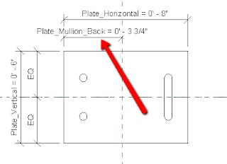
  2. In the Left view, dimension the object as shown below.  The exact values do not matter, but the EQ dimensions do; they will ensure that the plates remain centered on the reference plane.


  1. Switch to the Front view, dimension the thickness of the plate, then align the left edge of the plate to the vertical reference plane.  Lock the alignment by clicking the lock icon.


  1. In the Left view, create another extrusion.  This time create a 1/2" diameter circle as the cross section, place it 1 1/4" from the front of the plate and 1 1/4" from the horizontal reference plane and lock those dimensions.  Be aware that the lock icons often appear a significant distance from the dimensions when creating extrusions.


  1. In the Properties panel, set Extrusion End to 2" and Solid/Void to Void.  This will create a circular hole in plates up to 2" thick.  Click the Finish Edit Mode button to complete the void extrusion.
  1. Repeat the void extrusion process to create another hole below the horizontal reference plane and then create a slot shaped void on the right side of the plate.  Remember to lock the dimensions and that the Solid/Void options defaults back to Solid each time.  Your extrusion dimensions will not be visible unless you are creating or editing the extrusion.


  1.   Test the model by selecting the plate and dragging the grips to resize it; the plate should change size, while the holes and slot remain in a fixed location relative to the reference planes.


  1.   Undo any changes then save the file.
  2. Next, we're going to add parameters to the model so that the dimensions can be adjusted numerically.  Select the overall horizontal length dimension then, in the Options bar, hold down the Label button and choose <Add Parameter>.


  1.   In the Parameter Properties dialog box that opens, make sure Family Parameter and Instance are selected then name the parameter Plate_Horizontal.  The Instance option allows you to define the length of the plate for different kickers throughout the model.  Click OK


  1.   In the Left view, the horizontal dimension is replaced with a parameter having the same value as the prior dimension.


  1.   Repeat the procedure for the vertical and thickness dimensions naming the parameters Plate_Vertical and Plate_Thickness respectively.


  1.   The vertical reference plane will represent the back of the vertical mullion and we want this to be 1/4" away from the vertical centerline of the plate.  We'll accomplish this by setting up a parameter that is mathematically tied to the horizontal length through a formula.  First, create a parameter for the dimension measuring the distance from the vertical reference plane to the front of the plate.  Name this parameter Plate_Mullion_Back and make it an instance parameter.


  1.   In the Modify tab of the Ribbon, click the Family Types button to open the Family Types dialog box.  In the Formula column for the Plate_Mullion_Back parameter, enter the formula: (Plate_Horizontal / 2)-1/4".   This moves the front of the plate away from the vertical reference plane a distance equal to half the plate length minus 1/4".  It is imperative that the referenced parameter is spelled correctly, including capitalization, or the formula will not work.  Revit will revise the units to correspond with the project standards.


  1.   Click OK.  The formula now drives the value of the parameter.  Save the file.


  1. To create the second plate, it should be as easy as mirroring or copying the existing plate to another location.  Revit, however, does not consistently work when mirroring void extrusions and using the Cut Geometry tool will create the cut, but eliminate the usability of the parameters and constraints applied to the plate.  If mirroring or copying the plate does not work properly, follow the previous steps, in the existing file, modifying them to create a second plate on the opposite side of the Center (Left/Right) reference plane.


As you can see, there were a few steps required to build the parametric plates, but it can be used in many configurations without the need to model a similar same object for every situation.  In our next post, we will conclude the exercise by creating the parametric tube and tying the objects together.

Thursday, July 11, 2013

Creating Wind Load and Dead Load Symbols

Curtain wall anchors are used in two different capacities:  Dead load anchors are fixed connections that do not allow for movement relative to the structure to which they are attached.  Wind load anchors restrict movement in the horizontal direction but allow for vertical movement.  An extensive list of curtain wall definitions can be found at www.wheatonsprague.com/building-envelope-industry-terms.htm

 Wind load and dead load symbols are used, usually in section views, to identify where curtain wall anchors are located and which type they are.


There are no existing wind load (WL) and dead load (DL) symbols in Revit so this post will go through the steps of creating them.  We'll use a 1/4" diameter circle for the WL symbol and an equilateral triangle with a 1/4" base for the DL symbol; these shapes and sizes may be different depending on your company's, or the project's, standards.  Follow these steps to create the symbols using the Generic Annotation family template:

 1)  Click the Application button (the big R) > New > Family.

 2) In the New Family - Select Template File dialog box, double click on the Annotations folder, select the Generic Annotation.rft file, then click Open to open the template.


3)  We'll draw the outside of the WL symbol then fill it in with a solid black filled region.  In the Ribbon, click the Line button then, in the Modify|Place Lines tab that appears, click the Circle button.


  4)  Draw a circle at the origin with a 1/8" radius.


5)  To fill the circle with a solid pattern, you'll need to define the boundary for the region.  Click the Filled Region button from the Create tab.  Make sure Solid Black is selected in the Properties palette then click the Circle button from the Modify|Create Filled Region Boundary button.


6)  As you did in step 4, draw a 1/8" radius circle centered on the reference planes.  Revit should automatically snap to the perimeter of the circle when your cursor is placed over it.

 
 7)  In the Mode panel, click the Finish Edit Mode button.  The region boundary is filled with the solid black pattern.


8)  Zoom out, if necessary, select the note in the top, right quadrant of the template file then delete it.  Click the Application button > Save As > Family, name the file WL.rfa, choose a destination folder then click Save.


 9) Load the family into an open file.

 10)  Delete the circle then repeat steps 4 through 9 creating a triangle, with a 1/4" long base at the origin.  Do this by using the Inscribed Polygon tool, instead of the Circle tool in steps 4 and 6, set the number of Sides to 3, and set the distance from the origin to the top point to 9/64".


 11) Save the file as DL.rfa and load it into your project.

 12)  In the project file, scroll in the Project Browser, expand the Annotation Symbols category, expand the DL and WL entries, then drag the symbols into a view.


As you can see, adding customized annotation symbols to your Revit library can be a quick and easy process.  What other symbols do you think would be useful to add?

Thursday, June 27, 2013

Curtain Wall Door Scheduling Bug in Revit


One of the time saving tools in Revit is the ability to schedule doors and windows automatically.  Data in the schedule can include information such as mark, dimensions, quantity, and even the room names and numbers on either side of each door.  As the doors, and their parameters, change, the information is instantly updated in the schedule.  It was recently brought to our attention, by Timothy in Detroit, that there is a bug (or "feature" if you prefer) in Revit that prevents the room to/from data from appearing in schedule when the door exists in a curtain wall system created on the face of a mass*.

The project shown below has four wall elements: Wall, Wall by Face, Curtain Wall System by Face, and a Curtain Wall and each hosts a door object.


Room Separation lines are used to close the room on both sides of the doors and the areas were defined as rooms.

Each door is tagged and the Mark value added manually for the curtain wall doors.

Using the menu option View > Schedules > Schedules/Quantities opens the New Schedule dialog box where a Door schedule is created.


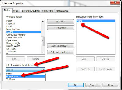
In the Schedule Properties dialog box, add the Mark field then, from the Select Available Fields From drop down list, choose From Room.  This provides additional, room-based fields that can be added to the door schedule.

 
Add the From Room: Number field to the Scheduled Fields column.  Repeat this after selecting To Room from the Select Available Fields From drop down list.


Click the Sorting/Grouping tab and choose Mark from the drop-down list and make sure the Ascending radio button is selected.  This organizes the schedule by door mark value from lowest to highest.  Click OK


The schedule is created displaying the default From Room and To Room Number value for each door.  This value can be overridden by selecting the other room from the drop-down list.  Changing the value in one column automatically swaps the value in the other column.


Notice that the door in the curtain wall system by face (door number 3) does not have a default value and no values are selectable from the drop-down list.


This is a bug that tends to leave a hole in you schedule and can affect the FM uses of a BIM model.  It has been reported and Autodesk is aware of the issue and (hopefully) will address it in an upcoming release or patch

 *This has been tested through Revit 2013.