Wednesday, April 8, 2015

Parametric Shadowbox Panels


Revit’s curtain wall tool is great in the fact that the actual glass/panel size interactively adapts to the size and configuration of the surrounding mullions. Wherever the curtainwall profile’s shape crosses the Center Front/Back reference plane, in the Profile-Mullion family, the panel is terminated.  That is a great solution when there is only a lite of glass or a panel surrounded by the mullions, but what do you do when a curtain wall panel includes a shadow box or insulation?  Those elements often don’t match the same extents that the glass or panel (see below) and may vary with the mullion conditions. 


Should a shadow box be created as a generic object as inserted separately?  That may be a viable solution, but it could also be time consuming.  This tutorial explains a method of incorporating the shadow box into the panel family and adding parameters to control the perimeter offsets.

1.  Start by opening the Curtain Wall Panel.rft template file.

2.  For this exercise, we’ll use a 1” monolithic glass element, but this can be as complex and detailed as you like.  Use the Extrusion tool and create a 1” thick rectangle in the Floor Plan view.  While still in the Create Extrusion mode dimension the thickness and lock the dimension then click the Finish Edit Mode tool in the Modify | Create Extrusion panel.


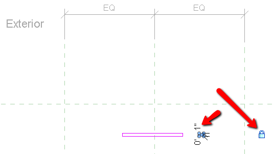
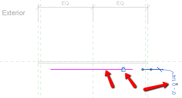
3.  Drag the left, right, and front grips to the corresponding reference planes and lock them.  This ensures that the glass maintains a constant thickness and flexes to match the extents created by the vertical mullions.


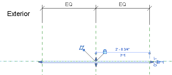
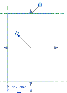
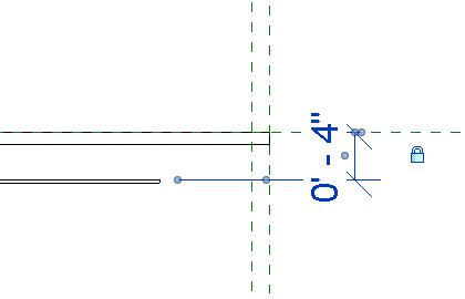
4.  In the Exterior elevation view, drag the top and bottom grips to the corresponding reference planes and lock them as well.  This ensures that the glass flexes to match the extents created by the horizontal mullions.


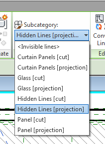
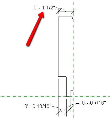
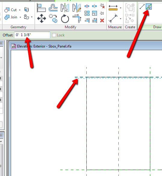
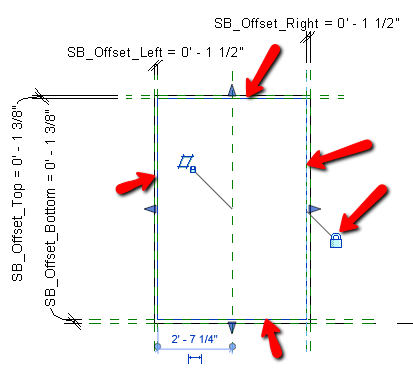
5.  We are going to set the initial offset distance for the shadowbox at 1 3/8” on the top and bottom and 1 1/2” on the sides.  These will be adjustable through the use of parameters.  Start by creating offset copies of the existing reference planes inward, as described.  This is done a bit differently than the procedure used to offset lines.  Instead of using the Offset tool, click Create > Reference plane from the Ribbon, click the Pick Lines icon, enter the Offset value, then hover over the existing reference plane, slightly inward until you see the ghosted ref plane to be created, then click.


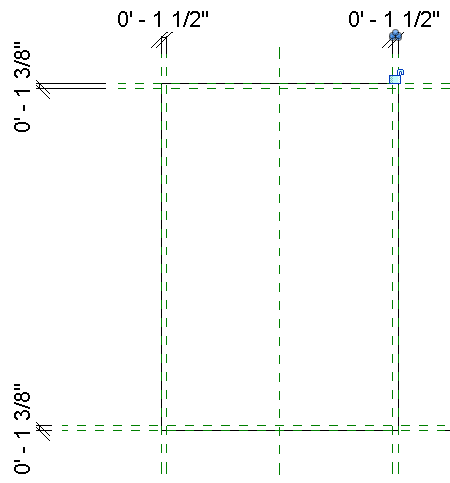
6.  Dimension the distances from the original reference planes to the offset reference planes but do not lock the dimensions.


7.  Select one of the dimensions, click the Label drop down menu and choose <Add parameter>.
 

8.  In the Parameter Properties dialog box that opens, choose Family Parameter, enter a descriptive name, select Instance (so the value can change for each infill occurrence as needed) and select a group that the parameter will appear in, and then click OK.
 

9.  The parameter appears with the default value.


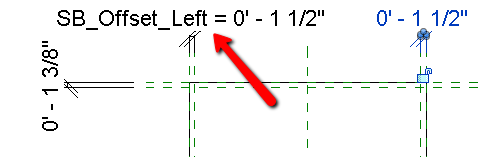
 10.  Repeat the process with the remaining dimensions, giving each a unique name.


11.  In the Floor Plan view, create a rectangular extrusion within the offset reference planes and behind the glass – this is the shadowbox panel.  While still in the Create Extrusion mode, dimension the thickness of the panel and lock the dimension. Click the Finish Edit Mode icon when you are done.


12.  Add a dimension from the Front reference plane to the front face of the panel and adjust the dimension as required.  If necessary, this could also be a parameter driven distance if it may vary over the course of the project.


13.  In the Front view, select the panel, drag the grips to each of their respective offset reference plans and lock them.


14.  Save the family then load it into a project containing a curtain wall then replace some existing panels with the new panel.  Note how the shadow box panel may not align properly with the sides of the mullions.
 

15  Select one of the panels and the parameters that were created appear in the Properties panel.  Select and adjust the parameters as required.


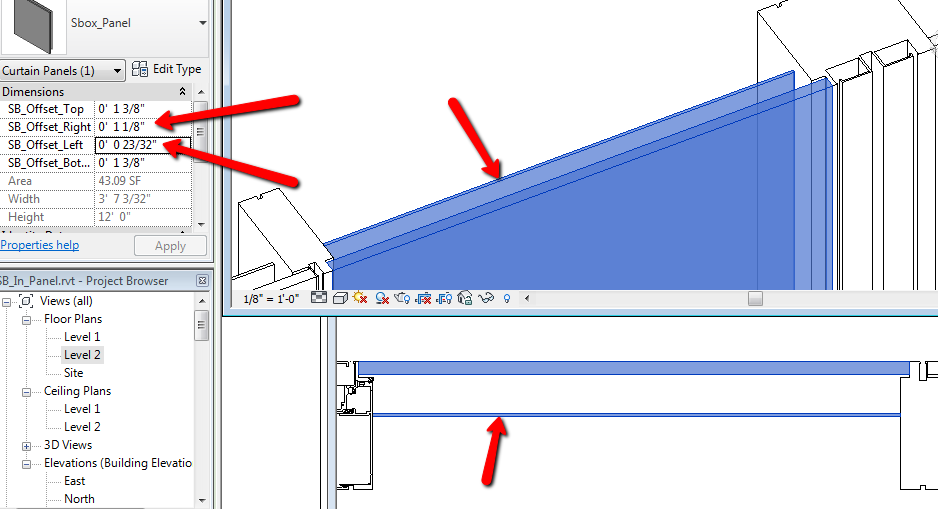
As you can see, creating adjustable shadow boxes as components of curtainwall panels is a simple and straightforward procedure and a similar procedure would be used to incorporate insulation into the panel family. By investing a little prep time, you could save a good amount of labor down the road.

Thursday, February 19, 2015

Adding Cross-X Lines to Unitized Panel Families


In a unitized curtain wall system, when looking at an elevation view, it isn’t always easy to determine the extents of any particular unit.  This can be even more difficult with the introduction of doors, windows, L-shaped units and  false-stack conditions.  By adding dashed lines, called cross-X lines, to the extents of the unit, it becomes easier to determine the limits of each unit.  This tutorial will cover adding cross-X lines to a Curtain Panel family in Revit.

                  
 The cross-X lines need to appear in elevation and 3D views and flex as the unit flexes to accommodate changes in height and width.  In the Curtain Panel family, we’ll start with a typical 3-lite unit and add the model lines.


1.  Model lines are drawn in the current reference plane.  In the plan view, either ensure that the Front reference plane is at the front of the unit or create a new reference plane.


2.  Switch to the Exterior elevation view.  In the Create tab, click the Set Work Plane button on the Work Plane panel to open the Work Plane dialog Box.


3.  In the Work Plane dialog box, select the Name radio button then select the reference plane that corresponds with the front of the unit.  Click the OK button.


4.  Click the Model Line tool.  Draw a line across the surface of the unit; the ends should be near the unit extents but do not place them precisely yet.


5.  Zoom in to one corner of the unit.  Select the model line to expose the grip then drag the grip to the corner of the unit.  The line may attempt to restrict the endpoint’s position to remain along the same vector as the line.  If necessary, press the Tab key to allow a 360 degree freedom of movement.  When the Endpoint grip highlights, release the mouse button.


6.  When the lock icon appears, click it to lock the endpoint of the model line to the element that was snapped to.
7.  Repeat the process at the opposite corner.


8.  Repeat the process for the model line that runs in the opposite direction.


The cross-X lines should appear different than the continuous lines.  In this case, we’ll assign them to the Hidden linetype.


9.  Select both model lines; this will open the Modify|Lines contextual tab.  Expand the Subcategory drop-down list then choose Hidden Lines (Projection).


10.   Select both model lines again then click the Edit button in the Graphics area of the Properties palette.


11.  In the Family Element Visibility Settings dialog box that appears, uncheck the Plan/RCP and Left/Right options to prevent the cross-X lines from appearing in those types of views. This affects the family when it is loaded into a project and not as it appears in the family editor.  Click OK.


 The unit now has cross-X lines that flex with the constraints of the curtainwall panel and are visible in elevation and 3D views


Friday, September 19, 2014

Controlling Embed Visibility Using a View’s Detail Level


In the building envelope industry, embeds are structural elements, cast into the concrete floor, and they bear the load of the curtain wall.  Companies, such as Jordahl and Halfen, make and supply cast-in channels that are often used as embeds and it is also common that project-specific embeds are designed.  In this tutorial, we will look at a method of displaying different elements of a custom embed depending on the Detail Level of the current view.

The embed that we’ll be using is made up of 6x8 angle, end plates to keep the concrete out, headed studs to tie-in to the anchor (the feature that connects the embed to the curtain wall), and rebar tails to increase the strength of the embed.


Why is it necessary to model to this level of detail?  In many cases, it is beneficial for clash detection and data extraction.  The size of the “box” and location/length of the rebar tails can identify conflicts with floor decking, columns, or other structural elements.  The appearance of the headed studs can ensure proper connection with the anchor and the elements, if created properly, can appear in schedules.

At larger scales, it’s important to see where the embeds are located, but the location and orientation of the rebar tails and studs is not.  These features may even become unreadable or blotchy.  At smaller scales, the appearance of the rebar tails and studs become more important and easier to distinguish.

To customize the visibility of the individual elements, we’ll start by selecting the headed studs then clicking the Edit… button for the Visibility/Graphics Overrides option.


This opens the Family Element Visibility Settings dialog box.  In the Detail Levels area, we uncheck Coarse and Medium to prevent the studs from appearing in any view that isn’t set to Fine.  


After clicking OK, we’ll select the rebar tails then repeat the previous procedure, this time unchecking only the Coarse option.


The embed is loaded into a scene and placed appropriately.  In this case, as is usually done in embed plans, the Bottom Offset and Level Offset values in the View Range dialog box are set to -1’-0” to allow the embeds to appear in the current view, rather than as an underlay.


As you can see, with the view’s detail level set to Coarse, only the angle and end plates are visible.


In a larger scale, the Medium Detail Level may be more appropriate.  This allows the rebar tails to appear in the view.


Finally, at a scale where the Fine Detail Level is best, the headed studs appear.


As you can see, by defining which elements are to appear at which detail levels, you can control how a single object appears in different views.  This also allows you to create objects with fine details that would be lost at larger scales while adding quality and accuracy at smaller scales.

Wednesday, July 30, 2014

Accurate Profiles Equal Accurate Curtain Walls


 The basic workflows for creating and assigning mullions to a Revit curtain wall are fairly straightforward.  You can either design a mullion type, with a specific mullion profile family designated in the Profile parameter, then assign that type to a curtain grid line or select an existing mullion on the curtain wall, duplicate the type, then assign a new profile to that mullion.  Profiles are assigned in the Type Properties dialog box.


In the mullion profile family file, there are two reference planes and both have their positions pinned by default.  At intermediate curtain wall grid lines, the vertical reference plane in the profile family is aligned with the grid line while the horizontal plane is aligned to the front of the curtain wall.  In jamb, head, or sill conditions, the edge of the profile is aligned to the edge of the curtain wall so that the entire profile is enclosed within the extents of the curtain wall.


The image below shows a 20’-0” long curtain wall with four vertical mullions in place.  The continuous dimensions, along the top and bottom, both add up to the total length of the curtain wall, but the first and last dimensions of each string are different.


What is causing the discrepancy?  The top string of dimensions is measuring to the center of the mullion as defined by the location of the vertical Center Of Mullion reference plane in the mullion family file. The bottom string of dimensions is measuring to the horizontal midpoint of the vertical mullion.  These should be in the same location, but in this instance, they are not.  Let’s take a look at the mullion profile.


As you can see, the mullion profile is not centered on the reference plane.  This is a situation that we’ve encountered, on occasion, when using content provided by third parties.


Why is a small dimensional inaccuracy a concern?  Mullions, anchors, kickers and embeds are usually aligned to their respective center lines.  If one of these is not located properly, then it may cause a clash at each occurrence which can add thousands of clashes to a project that would need to be addressed.
To remedy this, we can’t simply select the left-most line of the profile and change the dimension; this would result in a non-symmetrical and inaccurate  mullion.  Instead, we’ll delete half the profile, fix the remaining half, and then mirror the lines to complete the profile as shown here:

       1.       Delete or trim the side of the mullion that is shorter than the other.


       2.      Add and lock any horizontal dimensions that must remain constant.


       3.      Change the overall length


       4.      Select all of the lines (hover over one, press the Tab key, then click the left mouse button) then use the Mirror – Pick Axis tool from the Modify panel to mirror them about the vertical reference plane.


       5.      It’s a good practice to use a few lines as possible in your profiles.  The four short, horizontal lines that touch the vertical reference plane can be reduced to two lines by deleting one and stretching the other at both ends of the mullion. This will also eliminate an unnecessary vertical line in your elevations.


       6.      Save the family then use the Load Into Project tool to load the profile family into the Revit project.  In the Family Already Exists dialog box, choose either the Overwrite The Existing Version or Overwrite The Existing Version And Its Parameter Values option, depending on whether the profile has parameters included.


       7.      In the project, the dimensions measuring to the centerlines and the dimensions measuring to the midpoints are now equal.


Accurate curtain wall mullion profiles are essential to creating accurate curtain walls in Revit.  A little time spent ensuring that your profiles are correct at the beginning of a project can prevent headaches and reduce revision time later in the project’s lifespan.