Monday, February 25, 2013

Custom Profiles

Anilkumar Govindan Nair, from the Facade (curtain wall) engineering group on LinkedIn, asked whether it was possible to customize the aluminum profiles in Revit curtain walls.  It certainly is.  The curtain wall mullions that ship with Revit are very generic and not suitable for detailed, manufacturer specific projects.  In this exercise, you will learn how to create a custom vertical mullion profile and assign it in a project.  Before you start this exercise, have a project ready that has a curtain wall with at least one vertical grid line and set the units to Feet and Fractional Inches.

1)  Click the Application button (with the R at the top-left corner of the user interface) > New >Family.  In the New Family - Select Template File dialog box, click Profile-Mullion.rft.  This opens a new file using the template for mullion profiles.


The template consists of two reference lines; the vertical ref line represents the center of the mullion while the horizontal ref line represents the face of the curtain wall.  Everything above the horizontal line will be behind the face of the CW and everything below will be in front to the CW.


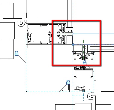
We'll draw a 3" x 6 1/2" mullion with a 1" cap.  A 1" wide glass pocket on the left side (as seen from the front) and a 1 1/4" glass pocket on the right.

2) Zoom in to the intersection of the reference lines then click the Line button in the Home tab's Detail panel.  Use the Rectangle tool to draw a 3" x 7 1/2" rectangle.  This is the beginning of the mullion profile to be used in your curtain wall.


3)  Use dimensions and constraints to center the profile on the vertical ref line and extend it 1" in front of the horizontal ref line.

4)  Draw a horizontal line on top of the horizontal ref line then offset it 1" toward the top of the window.  Make sure the Copy option is checked for the Offset tool.  The figure below shows the first horizontal line offset.

5)  Offset the left vertical profile line inward 3/4".  Click on the Split Element tool from the Modify panel of the Modify tab then click on the left, vertical profile line between the two middle horizontal lines.  This breaks the vertical line into two lines at the point where you click and allows you to trim the line in two locations without drawing another line.


6)  Use the Trim/Extend To Corner tool to trim the profile as shown below.  Remember to click on the portion of the line that you want to retain.


7)  Repeat the process on the other side of the profile but with a 1 1/4" gap for the glass pane.  It's important to make sure there are no overlapping lines, gaps between lines, or open ended lines.

Wherever any profile line crosses the horizontal reference line, that is the point that the curtain wall panel will terminate at the vertical.  Having the horizontal profile line on top of the horizontal ref line may cause an issue.  To prevent this, we'll widen the gap for the glass panes by 1/256".

8)  Zoom in to the horizontal lines that overlap the horizontal reference line.  Click the Line tool and then the Offset tool and make sure that Copy is unchecked and the Offset distance is set to 0' 1/256"; this will force the adjacent lines to adjust their lengths to match the new line locations.  Offset the lines toward the cap then save the file.  For this exercise, the profile is named Vert1.


9)  Click the Load Into Project button from the ribbon and load the profile into the project that you want to use it in.

10)  In the project that you want to add the new profile, click Home > Mullion then, in the Properties panel, choose Rectangular Mullion then click Edit Type.

11)  In The Type Properties dialog box, click the Duplicate button then name the new mullion type in the Name dialog box that opens.  In the figure below, it was named 1_1-25_Vert.

In the Type Properties dialog box, click the Value field for the Profile option and choose the new profile that you created and loaded into the project.  Click OK.  This assigns the new profile to the new mullion type.


12)  Click a grid line.  The new mullion type is applied to the curtain wall at the grid line location.


Adding custom mullion profiles is a straightforward procedure and gets faster with practice and when new mullions are similar to those that you've already created.  One thing that you may notice is that there may be more profiles in a project than you expect.  A mullion with a different cap, a wider glass pocket, or a deeper system requires an additional profile.  The good news is that the more profiles that you create now, the fewer that you may need to make for the next project.

Tuesday, February 19, 2013

Mullion Halves

In the prior post, Wall Joins, John enquired about my work procedures and using "half the mullion" on adjacent walls. Here's his actual question:

"Jon
How does half a mullion work? I assume you would still have to dis-join the walls still. Plus half a mullion on each wall creates (in my mind) an "L" shaped mullion and not a square shaped mullion. Personally I use one curtain wall without a mullion and the other with the "square" end mullion. Then I just align the curtain wall mullions together (outside faces). Everything from that point on looks perfect in 2D views... and even in 3D.  John"


John,
 We accomplish this by creating the profile for the male mullion half and assigning it to one wall and assign the female half to the adjacent wall.  The end points of the walls need to be separated when the mullions are assigned but are moved together after.  The figure below shows half of one mullion at an outside corner.


The figure below shows the adjacent curtain wall with the other mullion half assigned as the mullion profile.  Remember, the endpoints should no be co-located  when assigning the millions.


When finished, and the endpoints share a common location, the corner looks like the figure below.


Why is this preferable to assigning a single mullion to one curtain wall and leaving the adjacent curtain wall without a mullion?  That would require that the edge handle of the CW without the mullion to be manually aligned to the edge of the mullion where it crosses the panel's path; a feature that should be automatic in Revit.  Changes to the mullion profile won't necessarily be reflected in the open-ended CW and is an opening for errors.  The figure below shows a similar scene with a single, full mullion at the edge of one of the curtain walls.


Thursday, February 14, 2013

Wall Joins

Welcome to the debut posting for the CurtainwallBIM blog.  Our software of choice is Revit and our goals are to address any BIM related curtain wall issues, disseminate CW related information, and to help solve any problems ourselves or through dialog with other blog followers.  If you see a problem, or a better solution, please feel free to jump in and add your two cents.  We'll start by demonstrating the solution to the problem of curtain walls automatically joining when their end nodes get close to one another.


Disallow Join to Prevent Curtain Walls From Attaching

  In most cases, at an inside or outside corner condition, the ends of the adjacent Revit curtain wall objects should meet.  A common issue arises when the two curtain wall objects end near each other, but are not intended to meet as shown below.


  In this situation, when moving the endpoint of one CW object near the other, Revit will understand this to mean that the two walls should be joined and will move the endpoint of the unselected wall until it matches the endpoint location of the selected wall forming an intersection as shown below.  This may cause a warning dialog box to appear if it overrides constraints for one of the curtain walls. 


  To avoid this situation, follow these steps:

1)      Before moving the endpoint of one of the walls, select the wall then right-click on the blue circle at the endpoint.  If you right-click anywhere except over the blue circle you will get a different menu,
2)      From the menu that opens, select Disallow Join.   

  
3)      Repeat the process with the adjacent wall - both walls must have Disallow Join turned on.
4)      Move the endpoints of the wall as required and they can be positioned without regard to the other wall's endpoint.

If the design changes and you need to join the walls, you can either right-click on the endpoint and choose Allow Join from the menu or click on the T-shaped icon that appears near the endpoint when the wall is selected.


This procedure works in a similar manner when curtain walls butt into each other rather than forming an intersection.