Tuesday, March 20, 2018

How to make non-vertical Curtain Walls in Revit

In Revit, Curtain Walls cannot simply be tilted or rotated like the rest of the walls.  They need to be totally vertical.  So making the sloped or horizontal curtain walls that architects design can be difficult.  To do this we are asked to use the Curtain System tools to create these walls or ceilings.  The curtain system tools are not the same as the curtain wall tools and so it makes this process difficult.  It can be difficult to get the corners to connect properly.  Because of this, it can take a few tries to get everything to be lined up. 

 One key to getting everything to align properly is to preplan your modeling.  Both curtain walls and the curtain system use centerlines to control their placement.  The walls can be edited and moved much more easily than the curtain system.  The system is placed by face of a massing element.  To edit the final curtain system you need to edit the Mass and “Update to face”.  Only then can you see if the horizontal or sloped surface landed where you wanted it to.

 Things to remember when setting up your mass:

Make the planer surface locations reside at half the thickness of the wall system.  The perimeter needs to align to the outer edges.

If you are dealing with a single surface, keep your mass simple.  It’s easier to edit that way.

Things to remember about corners and mullions that end up misshaped:

It is frequently easier to build in-place little elements than to try to get the Revit ‘Curtain System’ tools to make things go as you wish.  Sometimes the standard Curtain System controls simply cannot do it.  Don’t be afraid of in-place elements.


Set up either a level or a named reference plane at the height that you need the curtain system to be located.  If it needs to be at an angle then it must be a named reference plane.  In this case we are using Level 3.


Under the “Massing and Site” tab, select “In-Place Mass”.


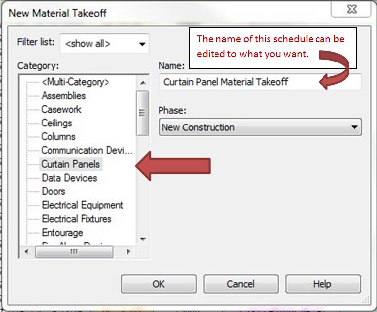
Give the Mass a name.


Set the Work Plane to the named reference plane or to the level that you set up.


Go to the 3rd floor plan view, or to a view that you can best see a perpendicular view of the Mass that you are about to make.  Place the lines of the new Mass at the edges of the area that you need the curtain system to occupy.  Think of this as a wall profile.  The perimeter edge controls the outer limit of the system when it is created. 


Select the “Finish Mass” button.


The Mass is adjustable.  You can use the arrow handles to change the size or align to elements if you choose.


Go to a 3d View to access if the Mass turned out as you planned. 

 
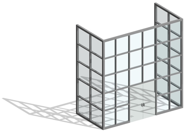
Zoom in on the vital areas to be sure that your Mass is aligned as you need it.  In the image below notice that the Mass is placed at one half of the thickness of the upper mullion on its lower boundary.  The Mass is aligned to the outer edges of the adjacent curtain walls in plan.  This is done because the curtain system goes in similar to a curtain wall.  Outer Mullions know to stop flush with the edge.  System or Wall centerlines define the placement of the mullions and glass.


Select “Create Form” and then “Solid Form”.  Depending on your view, you will see a multi directional control appear.  It can be used to adjust the size of the mass.


Rotate the model to allow access to the surface that you want to apply the curtain system to.  Select the bottom of your new Mass, as shown below.  You can select one, mulitple or all of the surfaces of the Mass.  We just need one for this exercise.


Now that you have selected which surfaces you want to place the curtain system, select “Create System”.  Revit now puts the system in that place.


The newly applied system might not align exactly as you wish.  There are a few things that can still be edited in the system at this point.  Curtain grids can be adjusted as they are with curtain walls.  Many things in a curtain system are by default locked.  I recommend using the crossing selection box to select everything in the area that needs edited, and unpinning it all.  Otherwise the grids and mullions will not be editable.


Once the things are unpinned you need to expose the grid lines.  They are normally difficult to select because they hide behind the mullions.  With a normal surrounding selection box, select the mullions that need to be realigned.  Use the filter to be sure that you only have Curtain Wall Mullions selected.  Use the Temporary Hide button to hide the mullions.  Now when you hover the mouse over the curtain grids they are easy to select.


Uncheck everything except the mullions.


Temporarily hide the mullions. 


First select the line that you want to align to.  Then select the second line to align it.


Continue the process to get the rest of the curtain grids aligned.  When you need to add or delete some of the curtain grid lines, they work in the same manner as the curtain walls.  


To add additional grid lines, under the Architecture tab, select “Curtain Grid”.  When you float your mouse by an edge of the system Revit shows temporary dimensions to let you know where the new grid line will be.  You can edit the location of that line after it is in place.  See instructions earlier in this Blog.


Once the locations are as you want them, select the Temporary Hide button to unhide the mullions. Select Reset.


Select the Mass.  You can choose to hide or delete the Mass. If you think that you may need to edit the Curtain System lid in the future, then hiding the Mass is probably your best choice.  You can delete it and the Curtain System that used the Mass to be placed will remain, though it will have limited edit ability after the mass is gone.


Review your model to assure that things align as you wish.


The End.
 We welcome your comments and feedback.


Tuesday, January 23, 2018

Data Mining Your Revit Model

Data Mining Your Revit Model

 
Revit is Database software that uses graphics and geometry as part of its system.  This leads to a very data rich model file.  There are a variety of different ways to get useful data from the Revit Model.  Revit can automatically schedule many elements of the model.  Revit can also do material take-offs of most elements that exist in the model.  Furthermore, Revit is also able to get useful information from reportable model data that doesn’t actually exist in the model.
 
There is information in the model that can be translated to provide different information that is useful to the manufacturer. For example; if I have the perimeter of a Curtain Wall Panel, then I can use that information to figure the length of gasket material or amount of adhesion material, and so on.  If we know how many fasteners it takes for the different mullion types and assemblies, we can add a parameter to include X amount of fasteners to each of the types. That information would only need to be added per type.  Then we can Schedule that information in the Curtain Wall Mullion Schedule.
 
Curtain Wall Panel take-offs do not automatically give perimeter information.  The following demonstrates how to mine your Revit model for useful information.  In this case we schedule the perimeter of the curtain wall panels.
 
Using Revit 2016 (This can also be done in earlier and later versions of Revit. Different year releases might not look identical.)
 
Step One
Click “View” then “Scheduled” then “Material Takeoff”.


Step Two
Select “Curtain Panels” from the “Category “ list.


Select “OK”
 
Step Three
Add the fields that you want to schedule.  Be sure to include “Height” and “Width”.  You will need them later to get the perimeter.  The “Family” and “Material Area” will also be useful for keeping track of types and ordering material.


Step Four
Select “Calculated Value”.  Name it “Perimeter”.  Set Discipline to “Common”, and Type to “Length”.


In the “Formula” area click the "three dot" button.   There you will see the parameters that can be used in a formula and are in the current scheduled fields.  First choose “Height” or “Width”.  Then choose the other. You can pick one at a time or just type in the formula by hand.  Be sure to match the text exactly or Revit won’t recognize it.  To get the perimeter you can use a few different formulas that will get the same result.  I use (Width + Height) * 2.  These formulas work like an Excel formula.


Edit the “Formula” field to show the calculation that you want.


Select “OK.”
 
Step Five
Once the fields are set, it’s time to determine how to show the desired data.  Sorting helps to arrange the data in a very useful spreadsheet layout.  Select the Sorting/Grouping tab to arrange the data for the spreadsheet.  Under the "Sort by:" pull down menu select Family and select the options you would like to use.  It is important to check the box for “Footer” and “Grand Totals”.  Whether everything needs itemized or not is up to you.

 
Step Six
Select  Formatting.” Be sure to check the “Calculate Totals” box at the bottom, for fields that you want the material length or area for.


Bonus Step
Sometimes we need lengths or areas in a different unit of measure for special circumstances.  Revit can easily deliver the information that you need in any of the formats that you see in the image below.  In the “Field Format” you can get this information in either Imperial or Metric.


Scheduling these factors is very useful for the folks involved in the project.  Area can be used for ordering material like glazing or coatings. Width can be used to find the longest span for the structural folks. Perimeter can be used for ordering material like gaskets or adhesion material.   


Once we think through the list of data that our manufacturers may need we can come up with a way to mine that information from our Revit “Database” Model.  We can get most of what we need from Scheduling the Curtain Wall Panels or Mullions.
 
I invite your questions or comments.