
In a unitized curtain wall system, when looking at an elevation view, it isn’t always easy to determine the extents of any particular unit. This can be even more difficult with the introduction of doors, windows, L-shaped units and false-stack conditions. By adding dashed lines, called cross-X lines, to the extents of the unit, it becomes easier to determine the limits of each unit. This tutorial will cover adding cross-X lines to a Curtain Panel family in Revit.


1. Model lines are drawn in the current reference plane. In the plan view, either ensure that the Front reference plane is at the front of the unit or create a new reference plane.


3. In the Work Plane dialog box, select the Name radio button then select the reference plane that corresponds with the front of the unit. Click the OK button.

4. Click the Model Line tool. Draw a line across the surface of the unit; the ends should be near the unit extents but do not place them precisely yet.

5. Zoom in to one corner of the unit. Select the model line to expose the grip then drag the grip to the corner of the unit. The line may attempt to restrict the endpoint’s position to remain along the same vector as the line. If necessary, press the Tab key to allow a 360 degree freedom of movement. When the Endpoint grip highlights, release the mouse button.

6. When the lock icon appears, click it to lock the endpoint of the model line to the element that was snapped to.
7. Repeat the process at the opposite corner.

8. Repeat the process for the model line that runs in the opposite direction.

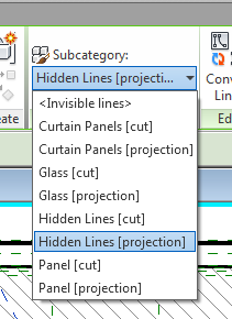
The cross-X lines should appear different than the
continuous lines. In this case, we’ll
assign them to the Hidden linetype.


The unit now has cross-X lines that flex with the
constraints of the curtainwall panel and are visible in elevation and 3D views
