Wednesday, July 30, 2014

Accurate Profiles Equal Accurate Curtain Walls


 The basic workflows for creating and assigning mullions to a Revit curtain wall are fairly straightforward.  You can either design a mullion type, with a specific mullion profile family designated in the Profile parameter, then assign that type to a curtain grid line or select an existing mullion on the curtain wall, duplicate the type, then assign a new profile to that mullion.  Profiles are assigned in the Type Properties dialog box.


In the mullion profile family file, there are two reference planes and both have their positions pinned by default.  At intermediate curtain wall grid lines, the vertical reference plane in the profile family is aligned with the grid line while the horizontal plane is aligned to the front of the curtain wall.  In jamb, head, or sill conditions, the edge of the profile is aligned to the edge of the curtain wall so that the entire profile is enclosed within the extents of the curtain wall.


The image below shows a 20’-0” long curtain wall with four vertical mullions in place.  The continuous dimensions, along the top and bottom, both add up to the total length of the curtain wall, but the first and last dimensions of each string are different.


What is causing the discrepancy?  The top string of dimensions is measuring to the center of the mullion as defined by the location of the vertical Center Of Mullion reference plane in the mullion family file. The bottom string of dimensions is measuring to the horizontal midpoint of the vertical mullion.  These should be in the same location, but in this instance, they are not.  Let’s take a look at the mullion profile.


As you can see, the mullion profile is not centered on the reference plane.  This is a situation that we’ve encountered, on occasion, when using content provided by third parties.


Why is a small dimensional inaccuracy a concern?  Mullions, anchors, kickers and embeds are usually aligned to their respective center lines.  If one of these is not located properly, then it may cause a clash at each occurrence which can add thousands of clashes to a project that would need to be addressed.
To remedy this, we can’t simply select the left-most line of the profile and change the dimension; this would result in a non-symmetrical and inaccurate  mullion.  Instead, we’ll delete half the profile, fix the remaining half, and then mirror the lines to complete the profile as shown here:

       1.       Delete or trim the side of the mullion that is shorter than the other.


       2.      Add and lock any horizontal dimensions that must remain constant.


       3.      Change the overall length
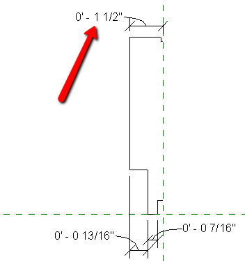


       4.      Select all of the lines (hover over one, press the Tab key, then click the left mouse button) then use the Mirror – Pick Axis tool from the Modify panel to mirror them about the vertical reference plane.


       5.      It’s a good practice to use a few lines as possible in your profiles.  The four short, horizontal lines that touch the vertical reference plane can be reduced to two lines by deleting one and stretching the other at both ends of the mullion. This will also eliminate an unnecessary vertical line in your elevations.


       6.      Save the family then use the Load Into Project tool to load the profile family into the Revit project.  In the Family Already Exists dialog box, choose either the Overwrite The Existing Version or Overwrite The Existing Version And Its Parameter Values option, depending on whether the profile has parameters included.


       7.      In the project, the dimensions measuring to the centerlines and the dimensions measuring to the midpoints are now equal.


Accurate curtain wall mullion profiles are essential to creating accurate curtain walls in Revit.  A little time spent ensuring that your profiles are correct at the beginning of a project can prevent headaches and reduce revision time later in the project’s lifespan.

Tuesday, May 13, 2014

Selecting Curtain Wall Components


Revit has specialized tools for selecting curtain wall-specific components based on the grid lines they are hosted by, their orientation, family, or the curtain wall host and this post explores those tools and explains how they are used.

Curtain walls, in Revit, are comprised of mullion, panel and gridline components.  These components can be selected individually by hovering the cursor over one or more objects, tapping the Tab key until the correct object highlights, then clicking the left mouse button.  Click here for a post on selecting specific curtain wall objects and some issues that may arrive.

 Like all objects in Revit, you can select the other object in the same family by right-clicking the mouse and choosing Select All Instances > Visible In View or Select All Instances > In Entire Project depending in the extent or requirements of the selection.  This can be used to change all mullions or panels from one family to another.


 To select all mullions, regardless of family, along a gridline, select one mullion on that gridline, right-click, then choose Select Mullions > On Gridline.  Your cursor must not be hovering over another object when you right-click or the context-specific menu will not show the Select Mullions option.


 All the mullions on the same gridline as the original are now selected.  You can use Select Mullions > On Gridline for both vertical and horizontal mullions


 This selection method also works when gridline segments are deleted by selecting the mullions on both sides of the missing span.


 Similarly, with a mullion selected, you can right-click and choose Select Mullions > Across Gridline to select all mullions that are parallel to the selected mullion and run between the same perpendicular gridlines.


 The other Select Mullions menu options include:

On Vertical Grid – Selects all vertical mullions on the current curtain wall.
On Horizontal Grid - Selects all horizontal mullions on the current curtain wall.
Inner Mullions – Selects all mullions that are not along the perimeter of the
                            current curtain wall (jambs, sills, heads).
Border Mullions - Selects all mullions that are along the perimeter of the
                              current curtain wall (jambs, sills, heads).
Mullions on Host - Selects all mullions in the current curtain wall.

Using any of the five methods listed above will deselect selected mullions if appropriate.

There are similar tools available for selecting curtain wall panels; however, they are slightly more restrictive.

After selecting a curtain wall panel, right-click (being sure not to hover the cursor over another object) and choose Select Panels > On Vertical Grid.  All vertical panels that are the same size as the original and run along the same vertical grid line are selected.  Revit will omit any panels that are not the same size.


Select a curtain wall panel, right-click and choose Select Panels > On Horizontal Grid.  All horizontal panels that run along the same horizontal grid line, even if they are of a different size, are selected. 


As expected, Select Panels > Panels On Host selects all the panels on the current curtain wall.

As you can see, there are several tools available to help you select Revit curtain wall components by family, vertical gridline, horizontal gridline, orientation or curtain wall.  I’m just waiting for the Select All Mullions Using The Old Die Designs And Replace Them With Mullions Using The New Designs button.  Now that would be helpful!

Monday, February 3, 2014

Why can’t I select my curtain walls in Revit?


Have you ever come across a situation where you can see the curtain wall elements in your Revit scene, but could not select them?  To make this a little more confusing, you could select the components of the curtain wall, but not the wall itself?  We have, especially when constructing the building envelope in files that were originally generated by someone else.  Fortunately, this is an easy fix.

Let’s take a look at the situation.
Zooming into a curtainwall, you place your cursor near the perimeter and expect the curtain wall to highlight as it usually does.


This time, the head mullion highlights, but not the overall curtain wall element.  Pressing the Tab key cycles the selection through the nearby curtain wall components, but not the host object.       


Trying to select the curtain wall with a selection window and filtering out everything except the wall itself seems like a solution but, as shown below, Walls are not shown as selected objects in the Filter dialog box along with the other objects.


What’s the problem?  It’s not the wall itself, but the Discipline setting of the current view.  With nothing selected, look at the Properties panel.  In the Graphics area, if the Discipline value is set to Structural, the curtain walls cannot be selected.  There are two solutions:  The first, and preferable, is to change the Discipline parameter of the view to Architectural or any option other than Structural.


The second, and not recommended, option is to select the curtain wall then, in the Structural area of the Properties panel, check the Structural option.  Curtain walls, by definition, are not load bearing and this solution may have ramifications regarding the structural design of the building.


We hope this information has been interesting and helpful.  If you have any questions regarding BIM and curtain walls, don't hesitate to ask.


Monday, December 30, 2013

Creating Parametric Kickers (Part 2)


Part 2: Creating the structural steel tube.

This is the continuation of the blog post post “Creating Parametric Kickers Part 1” found here.  The tube that ties the plates to a structural member is going to be a simple 3”x5”x1/4” steel tube with variable dimensions controlled by parameters.  The overall size of the tube will be accurate, but other features, such as the radii at the corners will not.

  1. Select the plates you created in the previous exercise and hide them using the Temporary Hide/Isolate tool at the bottom of the view window.  Repeat this in all viewports used in this exercise.
  2. Start the Extrude tool then, in the Front view, draw the extrusion profile shown below.  The vertical reference plane is the Center (Left/Right) reference plane at the origin of the template and not the Plate_Inside_Ref plane that was created in the prior exercise.  The dimensions are for reference only; delete them when you are finished.
 

  1. Set the Extrusion Start value to 1/4” and Extrusion End to 1’-0” then click Finish Edit Mode to complete the extrusion.
  2. Make the Left view current, click Create>Work Plane>Set, then select Center (Left/Right) from the drop-down list to reset the reference plane.
  3. Dimension the tube as shown below.


  1. Select the overall dimension, click the Label button in the Options bar then add a new parameter named Tube_Length.  Set this as a Family Parameter and select the Instance radio button.  Click OK

  1. Create another Instance parameter for the 1/4” dimension and name it Tube_Offset.
  2. In the Front view, dimension the tube as shown.  The EQ string dimensions will cause the height and width dimensions to flex evenly in both directions.


  1. Assign new Instance parameters named Tube_Width, Tube_Height, and Tube_Thickness to the appropriate dimensions.  The Tube_Thickness parameter is assigned to all four of the 1/4" dimensions.  Save the file.


  1. In the Left view, create a 1/2” diameter void extrusion, centered vertically and located 3” from the vertical reference plane.  Set Extrusion Start to -6” and Extrusion End to 6”.  This is for the hole and will accommodate widths as large as 12”


  1.  Complete the extrusion and you’re left with two holes penetrating the tube.


Part 3.  Putting it together


  1.  Unhide the plates in all views that it was hidden in and make the Floor Plan: Ref. Level the current view.

  1. Dimension from the vertical Center reference plane to the Plate_Inside_Ref reference plane and from the vertical reference plane to the second mirrored reference plane.  Do not make this a string dimension.

  1. Select one of the dimensions, create a new Instance parameter named Plate_Offset and assign it to the dimension.

  1. Open the Family Types dialog box and enter the formula Tube_Width/2 in the Formula column for the Plate_Offset parameter as shown below.  This will properly place the plate along the surface of the tube.  Click OK


  1.  Assign the Plate_Offset parameter to the other dimension to align the second plate.  Save the file.


  1. Open or create a file containing a curtain wall with vertical mullions in place.

  1. Load the kicker file into the curtain wall file then place them as required.  To place them, align the center reference plane of the kicker to the grid line then align the horizontal reference plane of the kicker (this is ¼” in front of the tube and invisible until the cursor is over it) to the back of the mullion.


  1.  Set the Tube_Width parameter to the same dimension as the width of the vertical mullions then make any final adjustments to the kickers using the parameters in the Properties palette.  Each parameter is an instance parameter so each kicker can be unique.


There are several additional parameters that can be added to your kicker to control other features such as the diameter of the holes or length of the slots.  Other features, such as shims, isolators or slip pads can also be added depending on the level of complexity required for the project.

We hope this has been an informative and useful  tutorial and, as always, feel free to post any comments or ask us any curtain wall related BIM questions.